
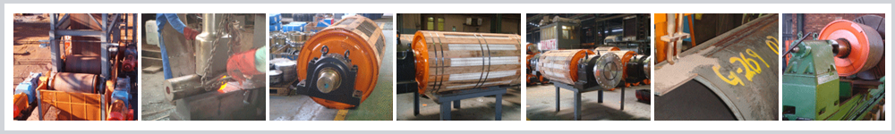
FABRICATION, FORGING & MACHINING OF COMPONENTS
Conveyor Pulleys
Conveyor Pulley Design
There are many elements to consider during the design of a conveyor pulley. The most important however is the design of the shafts. Other elements that need to be considered are the pulley diameter, the shell, the hubs and the locking elements.
1.0 Shaft design
There are three main factors that influence shaft design. Bending from the tensions on the conveyor belt. Torsion from the drive unit and deflection. The shaft therefore needs to be designed considering all three of these elements.
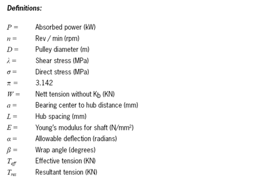
For the design of the shaft, based on bending and torsion, a max stress is used. This stress varies according to the material that is used for the shaft or according to the max stress allowed by the end user. Typical allowable stresses, for the most commonly used shaft material, are:
43 MPa for BS970 070M20 ( EN3 )
55 MPa for BS970 080M40 ( EN8 )
83 MPa for BS970 709M40 ( EN19 )
For the design according to maximum stress the following needs to be considered:
The industry uses additional safety factors for shaft design, as follows:
Load Factor (Kb = 1.5 to 1.75) and;
Torque Factor (Kt = 1.25 to 1.4)
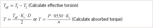
1.1 Calculate torque
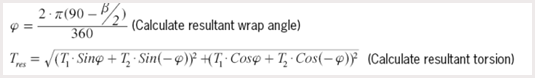
1.2 Calculate resultant forces
1.3 Calculate moments
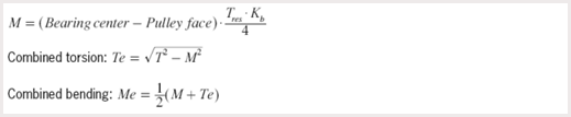
1.4 Calculate shaft
To calculate the shaft size from the above, the Guest (equivelent bending) and Rankine (equivalenf torsion) formulas need to be considered.
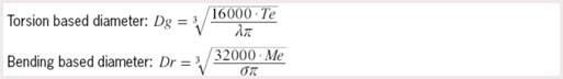
For the above formulas and are taken to be equal since the allowable direct stress ( ) is a fatigue case and the shear stress (λ) is not.
The third calculation determines free shaft deflection limit. This limit ensures that there is no excessive deflection of the shaft at the point where the bearings and the locking elements are fitted. The industry standard is 0.0015 rad to 0.0017 rad max allowable deflection.

The largest of the three possible diameters should be chosen and then rounded up to the next standard shaft size.
The table below gives a guideline on recommended pulley diameters, standard pulley face widths and bearing centers using belt widths from SABS 1669.
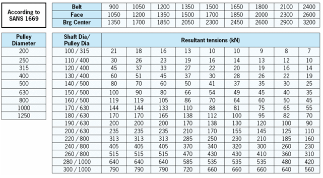
The recommended shaft sizes are calculated using 55MPa stress, 0.0015 rad deflection and no torque. This table is to be used as a guideline only.
2.0 Pulley design
There are various factors influencing the pulley diameter. The pulley diameter is mainly determined by the conveyor belt class, but the required shaft diameter also influences the diameter. A golden rule for the pulleys diameter is that it should be at least three times the diameter of the shaft.
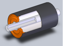
2.1 Pulley Types
There are two main types of pulleys i.e. the Turbine pulley and the TBottom Pulley. In both these types of pulleys the shaft is removable for easy maintenance.
The Turbine Pulley is well suited for low to medium duty applications with a hub designed to allow for flexing, thus preventing high stresses on the locking assemblies or welds.
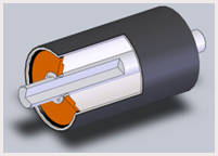
The T-Bottom Pulley is normally used for heavy duty applications with shaft diameters of 200mm and bigger. The main feature of this construction is a face welded pulley and thus the shell to hub weld is moved out of the high stressed area at the end plate
2.2 Pulley crowning
Full Crown: From the centre line of the pulley with a ratio of 1:100
Strip Crown: Crown from the first and last third of the pulley face with a ratio of 1:100 Crowning is normally only done on specific request.
2.3 Lagging
Various types of lagging can be applied to the pulley i.e. rubber lagging, flameproof (neoprene) lagging or ceramic lagging.
 Company
 Products
 Contact us
